I wanted to track my electric usage in real-time, and I’ve already have Home Assistant as my main smart home management system, so I wanted to make use of the Energy tracking feature that it provides.
Because my meter is located outside our house, I had to find a solution that runs on batteries.
I was looking into the Frient electricity meter, but couldn’t find any available anywhere. So I searched and found this DIY smart meter https://www.espruino.com/Smart+Meter
And to prolong the battery-life, I’m using 2 x D batteries instead of the small CR2032 battery.
UPDATE: After a couple of month using this. It became very unstable. It keept loosing connection to Home Assistant.
I ended up buying the Frient Electricity Meter Interface 2 – and this has been working perfectly.
What you need
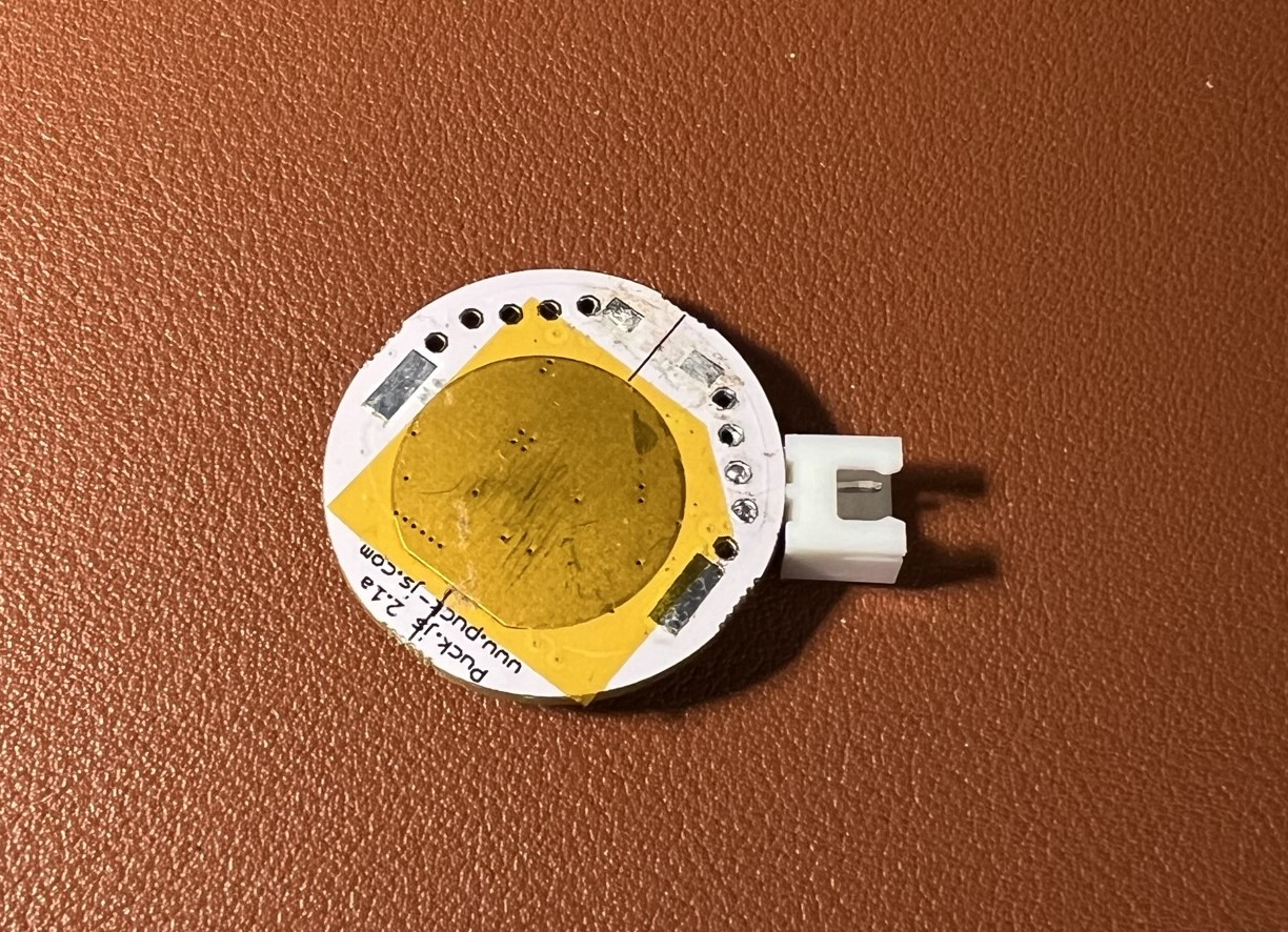
- Puck.js
- LDR sensor (GL5537)
- 2 x 15mm ring magnets
- D battery holder
- 2 x D batteries
- wire / 3d-printer
- optional: jst connector for the wire
3D printed casing
I started with 3d printing the casing for the LDR sensor and the Puck.JS
STL: https://www.printables.com/model/376244-puckjs-case-for-electricity-monitoring
I divided it in 3 part, for easier print.
– Casing for the LDR sensor and Puck.JS
– Magnet holder
– Meter alignment-piece, to block out any outside ligth when attached to the meter


Assembly
I started with removing the battery clip and the button from the Puck, for it to be more low-profile
– Put doublesided tape on one of the magnets, and attach it on the meters led.
– Solder the LDR and battery-connecter / wires together.
– Assemble the 3 3d printed pieces by glueing them together.
I added a red cap, so that the Puck’s led could shine throgh.


Coding
Get the code for the puck from github: https://github.com/aegjoyce/bthome-electricity-meter
You need to adjust the imp variable to match your meters. It should be printed on your meter. Something like: 1000 imp/kWh
If your Home assistant is setup correctly, it will find the device automatically.